Updated 2024
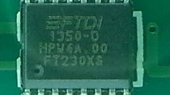
Adding USB connectivity to a microcontroller project can often significantly increase the overall cost. While popular solutions like the FT232RL and Arduino’s ATmega8U2/16U2 provide robust functionality, they can be more expensive than necessary for many applications. In this blog post, we’ll explore a more affordable alternative: the FT230X.
The FT230X: A Budget-Friendly USB-to-UART Bridge
The FT230X is a versatile USB-to-UART bridge chip that offers a cost-effective solution for adding USB connectivity to your microcontroller projects. Compared to the FT232RL, it provides essential UART functionality while reducing the number of external components required.
Key Advantages of the FT230X:
Lower Cost: Significantly more affordable than the FT232RL. Simplified Design: Requires fewer external components. Built-in ESD Protection: Protects against electrostatic discharge. Flexible Configuration: Can be configured using FTDI’s FT_PROG software.
Basic Circuitry for USB-Powered Devices
To get started with the FT230X, you’ll need a few essential components:
FT230X Chip Resistors (R1, R2): For edge rate control on the USB signal. Capacitors (C1, C2, C3): For filtering and decoupling. Inductor (L1): For noise reduction on the 5V power supply.
Connecting the FT230X to Your Microcontroller
The FT230X provides a simple UART interface that can be connected directly to your microcontroller’s UART pins. Additionally, the RTS# signal from the FT230X can be used to control the microcontroller’s reset pin.
Configuring the FT230X with FT_PROG
For advanced customization, you can use FTDI’s FT_PROG software to program the EEPROM on the FT230X. This allows you to fine-tune the chip’s behavior and unlock additional features.
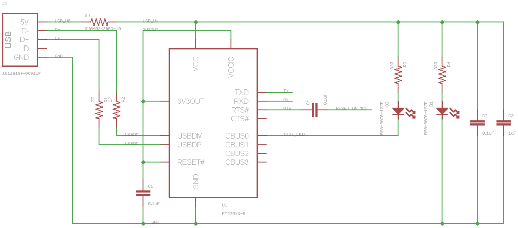
The above circuit is for a USB-powered device up to 100mA and 3.3V I/O on a microcontroller. This has to include the FT230X which draws around 8mA under normal operation. R1 and R2 are for edge rate control on the USB signal.
Capacitors to ground can be connected to the D- and D+ USB lines but are not completely necessary. L1 is an inductor to help keep noise off the 5V bus. The RTS# signal from the FT230X should be tied to the reset signal on the microcontroller being used though a small cap like C4. This signal can be set to be either active high or low depending on how your microcontroller’s reset signal functions.
Next week we will take a closer look at FTDI’s FT_PROG software to program the EEPROM on the FT230X to expand the FT230X’s functionality.